+86 15633683072
Consistent circumferential welds require more than a stable welding arc. Joint preparation, torch positioning, travel speed, welding parameters, and operator setup all affect the final result. Even when the welding process is mechanized, small variations in these factors can lead to uneven bead profiles, undercut, lack of fusion, or inconsistent penetration.
An automatic welding tractor helps control torch movement and travel speed, reducing some of the variations associated with manual operation. However, it cannot compensate for every problem in the welding process.
To improve pipe girth weld quality, manufacturers need to treat equipment, welding procedures, and workpiece preparation as one integrated system. This article examines the factors that influence weld consistency and explains how an automatic welding tractor can help improve results in practical production conditions.
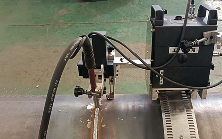
An automatic welding tractor moves a welding torch along a predetermined path at a controlled speed. Depending on its configuration, it may also support torch oscillation, adjustable torch positioning, or integration with a compatible welding power source.
Compared with manually guiding a torch around a pipe, mechanized travel can reduce variations in movement and make repeated welding operations easier to reproduce.
The main benefits include:
More consistent travel speed: Reduces unintended speed changes that can affect bead width and heat input.
Repeatable torch movement: Helps maintain a more consistent welding path around the circumference.
Reduced operator fatigue: Limits the need to guide the torch continuously by hand, particularly on large circumferential joints.
Repeatable settings: When the machine and power source support suitable controls, operators can reuse established settings for similar workpieces.
These advantages can improve automatic pipe welding quality, especially when the same joint configuration is produced repeatedly. The actual improvement depends on the starting process, equipment capabilities, joint preparation, and operator skill.
An automatic welding tractor is therefore best understood as a tool for controlling specific variables—not as a guarantee of defect-free welds.
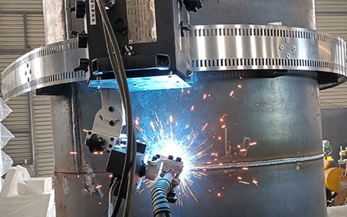
Travel speed influences how much heat is applied per unit length of weld. If other parameters remain unchanged, increasing travel speed generally reduces heat input per unit length, while decreasing speed generally increases it.
Excessive travel speed can contribute to insufficient fusion or an irregular bead profile. Travel that is too slow can cause excessive heat input, a wider weld pool, or other problems depending on the material, joint geometry, and welding position.
For consistent pipe girth weld quality, travel speed must be matched to the welding current, voltage, wire-feed speed where applicable, material thickness, and joint design.
An automatic welding tractor helps maintain a more stable travel rate, but the selected speed still needs to be validated through the applicable welding procedure and representative trial welds.
Practical check: Record the qualified or approved parameter settings for each relevant joint configuration. If bead width or penetration changes, investigate the complete set of welding variables rather than adjusting travel speed alone.
Torch angle affects arc direction, weld-pool behavior, and access to the joint. Incorrect positioning may contribute to uneven bead formation or poor fusion, particularly when welding around a pipe in different positions.
Before welding, verify:
The torch is correctly aligned with the joint.
The electrode or wire extension is appropriate for the process.
The torch angle remains suitable throughout the travel path.
The carriage and torch mount are secure.
The torch does not collide with fixtures or adjacent structures.
An automatic welding tractor can reproduce a properly established torch path, but it cannot automatically correct an incorrect initial setup unless the system includes suitable sensing or control functions.
During circumferential weld automation, check whether the torch position remains appropriate as the machine moves from the top of the pipe to the sides and bottom. The ideal setup depends on the welding process, joint geometry, and applicable welding procedure.
Poor joint preparation is a common reason mechanized welding fails to deliver the expected consistency.
If two pipe ends are misaligned, the root gap varies around the circumference, or the bevel geometry is inconsistent, the welding conditions change as the torch travels. A stable carriage cannot make an uneven joint geometrically uniform.
Before starting the weld, inspect:
Pipe-end alignment and mismatch.
Root gap around the circumference.
Bevel angle and root face.
Tack weld quality and spacing.
Surface cleanliness and removal of contaminants.
For multi-pass welding, consistent joint geometry also helps the operator maintain the intended pass sequence and bead placement.
Improving pipe girth weld quality therefore starts before the welding tractor is switched on. Proper fit-up and a repeatable preparation procedure reduce the number of variables that the welding process must accommodate.
Travel control is only one part of the welding system. Current, voltage, wire-feed speed, shielding gas, electrode or filler material, and other settings must suit the material and joint.
The appropriate values depend on the welding process, material grade, thickness, welding position, and qualified procedure. A parameter set that works on one pipe may not be suitable for another.
To improve automatic pipe welding quality, establish a documented welding procedure and verify that the power source and carriage operate within the required settings.
For example, if a weld bead becomes wider or narrower during a pass, possible causes include travel-speed variation, changes in joint geometry, inconsistent torch position, or unstable welding parameters. Investigating these factors together is more effective than assuming the carriage is responsible.
Shielding gas delivery and surface preparation also matter. Contamination, inadequate shielding, or unsuitable consumables can cause defects that mechanized travel cannot prevent.
Thick-wall pipe joints may require multiple welding passes. In these applications, each pass must be positioned correctly and deposited under suitable conditions.
Important considerations include:
Correct root-pass formation.
Adequate cleaning between passes.
Consistent placement of subsequent weld beads.
Interpass temperature control where specified.
Compliance with the required pass sequence and inspection procedure.
A welding tractor may improve travel consistency for a given pass, but multi-pass results still depend on the welding procedure and the operator's control of torch position and bead placement.
When circumferential seam welding involves multiple passes, confirm that the carriage can accommodate the required torch angle, access, and movement for each pass. Do not assume that a successful root pass automatically validates the settings for fill and cap passes.
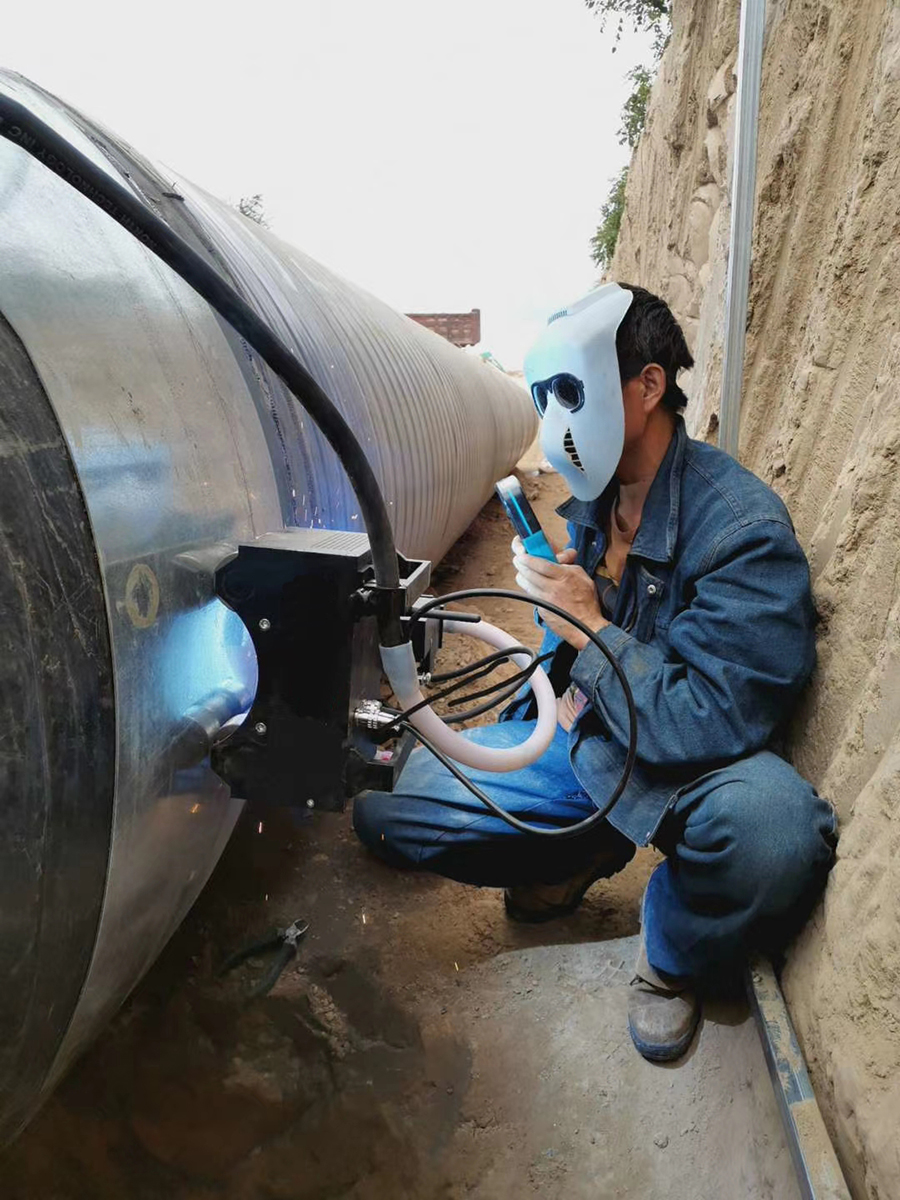
A repeatable setup process helps turn mechanized travel into reliable production results.
Clean the welding area and verify the joint dimensions, alignment, root gap, bevel, and tack welds. Correct unacceptable fit-up before welding.
Secure the track or carriage according to the manufacturer's instructions. Check the travel path around the full circumference and confirm that cables, fixtures, and surrounding structures will not obstruct movement.
For magnetic systems, verify that the base material and surface condition provide suitable attachment. Check the carriage's secure positioning before operation.
Confirm the required current, voltage, travel speed, wire-feed settings where applicable, shielding gas, and torch position. Use the approved welding procedure rather than relying on generic settings.
Where practical, test the setup on representative material and joint geometry. Examine the bead profile and perform the inspections required for the application before releasing the settings for production.
Observe carriage travel, arc stability, torch position, and weld-pool behavior. Record relevant settings and inspection results so that similar joints can be produced more consistently.
These steps help circumferential weld automation deliver repeatable performance without overlooking the process controls that determine weld quality.
For a related discussion of travel control and production performance, see automatic welding tractor efficiency testing, linking to the article Efficiency Test of Automatic Welding Tractor for Pressure Vessel Circumferential Seam Welding.
The table below provides a starting point for troubleshooting. The actual cause must be confirmed against the welding process, joint design, and inspection findings.
| Observed issue | Possible contributing factors | What to check |
|---|---|---|
| Uneven bead width | Inconsistent travel speed, torch position, or joint geometry | Travel settings, torch alignment, fit-up |
| Undercut | Unsuitable current, travel speed, or torch angle | Qualified parameters and torch position |
| Lack of fusion | Inadequate heat input, poor access, or incorrect technique | Joint preparation, parameters, torch angle |
| Porosity | Contamination, shielding problems, or unsuitable consumables | Surface cleanliness, gas delivery, consumables |
| Inconsistent penetration | Root-gap variation, alignment, or parameter changes | Fit-up, root preparation, welding procedure |
The distinction between a mechanical issue and a welding-process issue is important. If the carriage deviates from its intended path, investigate track alignment, mounting, drive behavior, or magnetic attachment as applicable. If the carriage follows the path correctly but the weld remains inconsistent, examine joint preparation, torch positioning, parameters, and shielding conditions.
A smooth-looking bead does not necessarily prove that a weld meets the required acceptance criteria.
Inspection should follow the project specification and applicable welding procedure. Depending on the application, verification may include visual inspection, dimensional checks, and specified nondestructive testing.
When evaluating circumferential weld automation, compare results across representative joints rather than relying on one successful demonstration.
Useful records include:
Workpiece material, diameter, and wall thickness.
Joint preparation and welding position.
Welding parameters and travel settings.
Setup changes or interruptions.
Inspection findings and any required repairs.
These records help determine whether the equipment and process are producing repeatable results under actual production conditions.
For large-diameter applications, the same principles apply: a stable travel path is valuable, but fit-up, torch access, welding parameters, and inspection remain essential. See automating large-diameter pipe circumferential welds, linking to How to Automate Circumferential Welds on Large-Diameter Pipes.
Start by controlling joint preparation, alignment, root gap, torch position, travel speed, and welding parameters. Use an appropriate automatic welding tractor to improve movement consistency, then verify the results through trial welds and the required inspection.
No. It can reduce variation in torch travel, but it cannot independently correct poor fit-up, contaminated surfaces, unsuitable parameters, or inadequate shielding. Weld quality depends on the complete process.
The main factors include joint geometry, material condition, welding parameters, travel speed, torch angle, shielding, and operator setup. Their relative importance depends on the material, welding process, and joint design.
Some applications can be highly automated, particularly when workpieces and joint configurations are repeatable. The required level of automation depends on access, joint variation, welding process, sensing and control functions, and inspection requirements.
No. Suitability depends on the carriage's operating range, mounting or attachment method, travel path, torch access, and the welding procedure. Confirm the actual workpiece dimensions and operating conditions with the equipment supplier.
Improving pipe girth weld quality requires control of the entire welding process, not just the carriage's movement. An automatic welding tractor can help maintain consistent travel speed and torch movement, but the benefits depend on accurate joint preparation, suitable welding parameters, correct torch positioning, and effective inspection.
The most reliable approach to circumferential weld automation is to establish a repeatable setup, validate it on representative joints, monitor the results, and document the settings that meet the required acceptance criteria. This allows manufacturers to use mechanized welding where it provides a real production benefit without treating automation as a substitute for sound welding practice.
Zhengzhou Kehui Technology Co., Ltd
Email: info@zzkehui.com





 Chinese
 English
 OA
OA Current location:
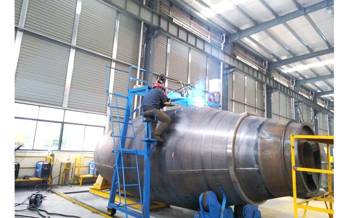 Concrete Mixer Drum Robotic Welding Solutions
  Automobile Body Production Line Welding Fixtures
  Automotive Body Welding Automated Manufacturing Solutions
  Free-Teaching Programming Welding Robot Cell For I Beam Welding
  No Programming Required Robotic Welding Systems for H beam Welding Line